Thermal sensor · IR window characterization
Window Calibration
Reference sweeps with an IR window glued to the front of an AMG8854M01, differenced against the no-window baseline at matched scene temperature. The window effect is real and scene-dependent, but neither run isolates transmission: the window sits at whatever air temperature surrounds it, not at the die temperature.
- Part
- Panasonic AMG8854M01 (35.6° FOV)
- Device ID
- cali.EGG68 (nRF9151)
- Window
- IR window, glued to the sensor face
- Target
- 1 in steel block, 3M black tape, insulated
- Reference
- PT1000 / Agilent 34401A — unmoved since the no-window run
- Standoff
- 5.5 cm → 35 mm FOV footprint
- Scene sweep
- 4.9 → 22.9 °C (PT1000)
- Die temp
- 25.2 – 26.7 °C
- Frames
- 238 / ~1 per minute, 2026-08-31/09-01 UTC
- Baseline
- no-window warm-up, 2026-08-29, 173 frames
Summary
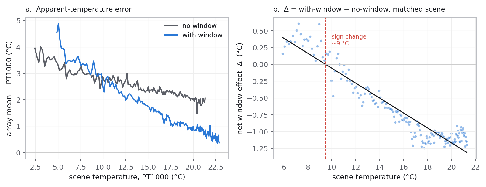
An IR window glued to the sensor face shifts the apparent temperature by a
scene-dependent amount: from +0.4 °C
when the scene is near 5 °C to −1.1 °C
when the scene is near 21 °C, crossing zero at a scene temperature of
about 9.5 °C. A pure transmission loss cannot do this:
with the window colder than nothing in view, it would pull every reading in
this range upward. The window was not at die temperature. Backing the window
temperature out of the radiometric model puts it near 10–14 °C
for the whole run — roughly the cold air pool in the chimney, and
12–15 °C below the die. A single warm-up sweep therefore returns
only the compound quantity (1−τ)·a ≈ 0.13,
where a is the unknown window-to-die coupling, not the transmission
τ itself. Isolating τ needs the window
temperature measured directly.
Window effect, cold scene
+0.4 °C
scene ~5 °C
Window effect, warm scene
−1.1 °C
scene ~21 °C
Sign change
9.5 °C
scene temperature
Compound coefficient
0.13
(1−τ)·a — not τ
The setup
Identical to the no-window warm-up: the same 1 in steel block, cooled and left to warm back to ambient over four hours in an insulated chimney; the same PT1000 on the same spot of the tape, not moved since that run, so the scene temperature is a shared reference between the two datasets. The only change is an IR window bonded to the front of the sensor. The comparison is frame-by-frame at matched PT1000 temperature — the contrasted-scene differencing approach of the thermography standards, run over a continuous warm-up rather than two fixed points [4][6]:
Δ(T) = GEwindow(T) − GEno window(T)
The no-window reading is modelled as a cubic in scene temperature fitted to the 2026-08-29 run. The sensor's dependence on its own die temperature is negligible over the range the die covered (about 0.005 °C per °C), so the roughly 1 °C difference in die temperature between the two nights does not affect the comparison.
The first six windowed frames are dropped. Frames 0–1 read
Δ = +1.2 and +1.6 °C with the die still
falling from 25.9 to 25.2 °C — the settling transient from
replacing the chimney over the block before logging started. It is gone by
frame 6.
The net window effect
Panel a overlays the apparent-temperature error with and without the window. Without the window the array mean sits a near-constant 2.5 °C above the PT1000. With the window that offset is scene dependent: larger at the cold end, and it crosses and goes negative as the scene warms. Panel b is the difference — the window's own contribution:
Δ = −0.111·Tscene + 1.05 °C
(equivalently Δ ≈ 0.13·(Tdie − Tscene))
| scene bin | n | Δ mean | die mean |
|---|---|---|---|
| 5–8 °C | 13 | +0.37 °C | 25.3 °C |
| 8–11 °C | 21 | +0.11 °C | 25.4 °C |
| 11–14 °C | 26 | −0.40 °C | 25.4 °C |
| 14–17 °C | 35 | −0.79 °C | 25.5 °C |
| 17–20 °C | 50 | −1.08 °C | 26.1 °C |
Why this is not the transmission
The radiometric model for a window in the path, under the assumption that the window and the surrounding environment share one temperature, is [4]
Tapparent = τ·Tscene + (1−τ)·Twindow
so the window's contribution is
Δ = (1−τ)·(Twindow − Tscene).
The measured Δ is positive at cold scenes and negative at
warm scenes, which means Twindow lies between
the cold and warm ends of the scene sweep — not up at the die. Solving
the model for the window temperature at three assumed transmission values:
| τ assumed | implied Twindow | die |
|---|---|---|
| 0.85 | 10 – 16 °C | 25.5 °C |
| 0.90 | 10 – 14 °C | 25.5 °C |
| 0.95 | 5 – 15 °C | 25.5 °C |
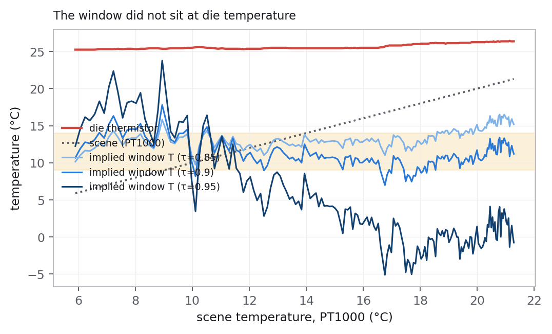
The sensor and its glued window are recessed about 8 mm into a 5.5 cm insulated well, looking down a cold air column onto a cold block. The window is convectively coupled to that column, not conductively locked to the die. It ran cold and roughly flat near the air-pool temperature while the block warmed underneath it.
Because Twindow is unknown and itself set by the
rig, the warm-up sweep is degenerate — the same degeneracy noted for
thermography windows, where the transmittance correction becomes indeterminate as
the window and target temperatures converge
[5]. Writing
Twindow = a·Tdie + (1−a)·Tscene
gives Δ = (1−τ)·a·(Tdie − Tscene),
and the fit returns only the product:
(1−τ)·a ≈ 0.13
The single number τ ≈ 0.89 that appears if the window
temperature is forced constant is a coincidental fit, not a measurement, and
is not used.
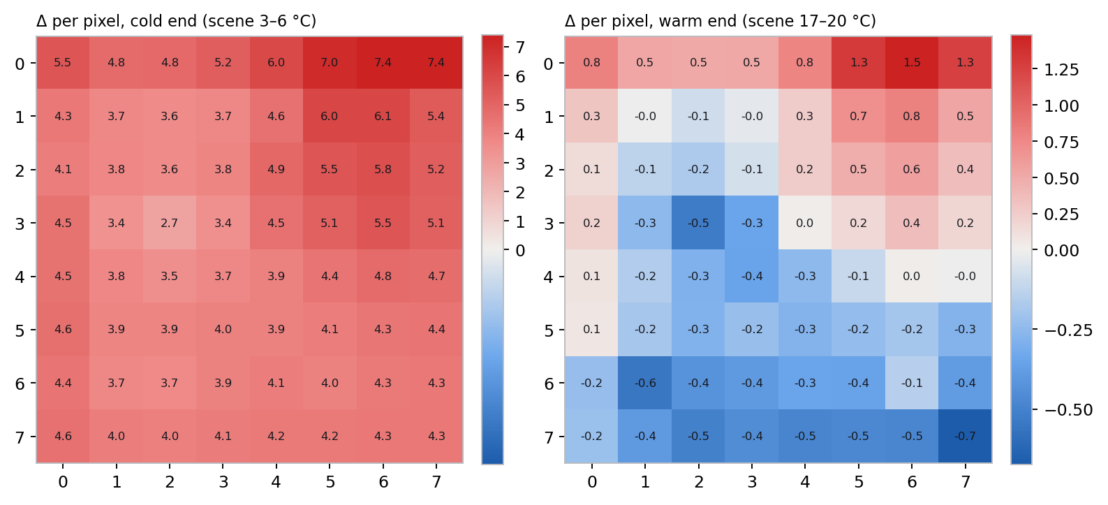
Per-pixel
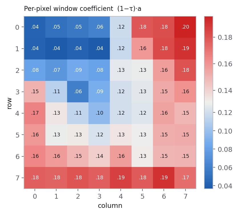
The compound coefficient (1−τ)·a fitted per
pixel: mean 0.131, standard deviation 0.044, range 0.04–0.20. It has
spatial structure — low along the top-left rows and columns, higher along
the bottom and right edges. The gradient is diagonal, not radial, so it is
more consistent with the window sitting at a slight tilt, or with a
temperature gradient across the window, than with angle-dependent
transmission — though oblique rays through a window are known to carry a
pixel-dependent transmittance [4].
It carries the same unknown-window-temperature caveat as the array figure and is
reported as qualitative.
pixels[] array.| 0.04 | 0.05 | 0.05 | 0.06 | 0.12 | 0.18 | 0.18 | 0.20 |
| 0.04 | 0.04 | 0.04 | 0.04 | 0.12 | 0.16 | 0.18 | 0.19 |
| 0.08 | 0.07 | 0.09 | 0.08 | 0.13 | 0.13 | 0.16 | 0.18 |
| 0.15 | 0.11 | 0.06 | 0.09 | 0.12 | 0.13 | 0.15 | 0.16 |
| 0.17 | 0.13 | 0.11 | 0.10 | 0.12 | 0.12 | 0.16 | 0.15 |
| 0.16 | 0.13 | 0.13 | 0.12 | 0.13 | 0.13 | 0.15 | 0.15 |
| 0.16 | 0.16 | 0.15 | 0.14 | 0.16 | 0.13 | 0.15 | 0.15 |
| 0.18 | 0.18 | 0.18 | 0.18 | 0.19 | 0.18 | 0.19 | 0.17 |
Re-test — raising the window out of the cold pool
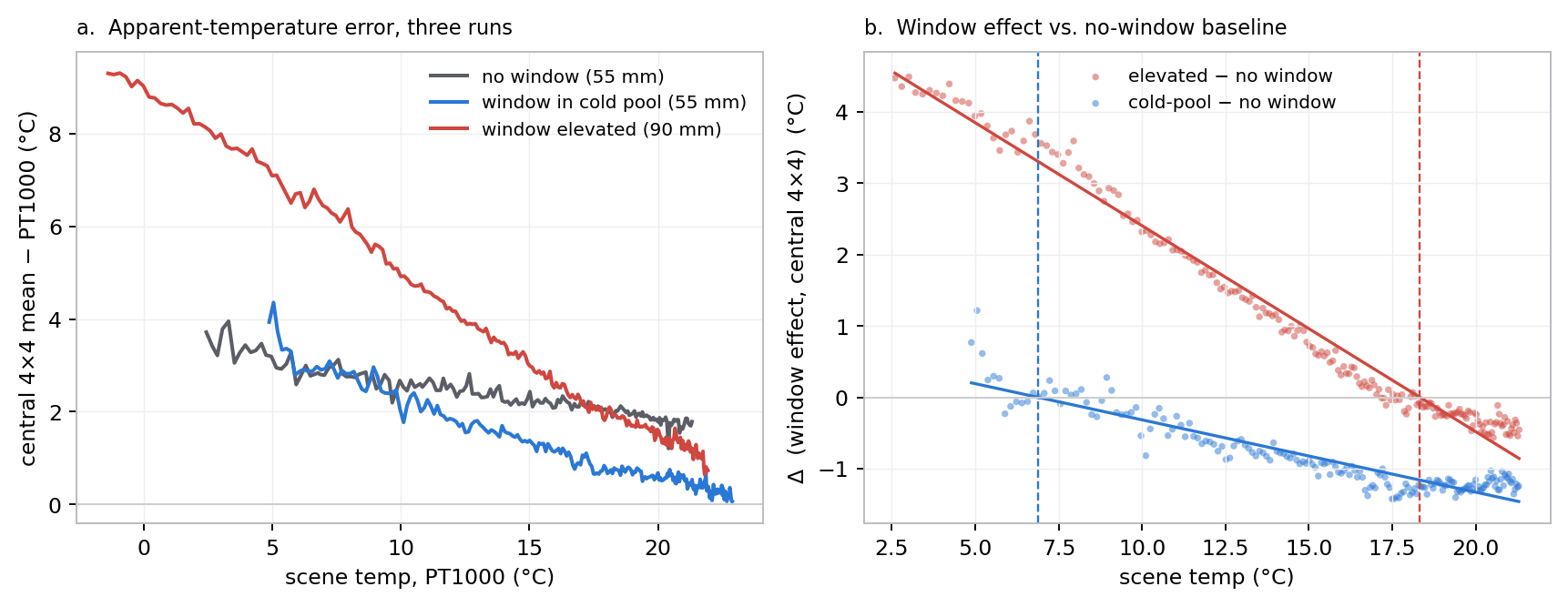
The first run left the window sitting in the chimney's cold air column. A second run (2026-09-02) repeated the warm-up with the sensor and window raised 35 mm, clear of that pool, to test whether the window would then track the die. Same block, same PT1000, same 2026-08-29 no-window baseline; standoff now ~9 cm, so the analysis is restricted to the central 4×4 pixels (the footprint barely covers the block at that height).
| run | slope vs Tscene | zero-crossing | Δ @ scene 5 | Δ @ scene 20 |
|---|---|---|---|---|
| window in cold pool (5.5 cm) | −0.10 | scene 7 °C | +0.2 °C | −1.3 °C |
| window elevated (9 cm) | −0.29 | scene 18 °C | +3.9 °C | −0.5 °C |
Since Δ = 0 when Twindow =
Tscene, the zero-crossing is the window
temperature. It moved from ~7 °C (the cold pool) to
~18 °C (room air) — not to the
~26 °C die. Raising the sensor swapped one air bath
for another. The window follows whatever air surrounds it; the slope also
steepened, because fully exposed above the chimney it couples to ambient
harder than when it was recessed.
Caveats: there is no no-window run at 9 cm to subtract the standoff change, and the per-pixel gradient suggests ~1 °C of the cold-end excess is geometry rather than window. The common-mode signal and the zero-crossing shift (7 → 18 °C) are not explained by geometry. Both runs point the same way: the bench cannot put the window at die temperature. A powered sensor runs its die above the room, and an exposed window sees the room. “Window = die” is a property of the deployment thermal design — a sealed metal enclosure at one temperature, or a deliberate conductive tie and a convective barrier — not something reproducible on the bench.
What this means for the product
The deployment sensor will also have a window bonded to it, so a window term is unavoidable. Two things follow from this run:
- The window bias is not a constant. Over a 15 °C scene span it moves by about 1.5 °C and changes sign. A fixed offset does not correct it.
- The correction needs the window temperature, not just the transmission. Assuming the window follows the die — the working assumption going into this run — is wrong for a recessed sensor looking at a scene well below its body temperature. How wrong depends on the mechanical design: a window flush with the enclosure wall, in contact with the enclosure, will couple closer to the die than this bench chimney does. That has to be measured in the product mechanics.
Until the window temperature is instrumented, the usable empirical result
is the compound slope: Δ ≈ 0.13·(Tdie − Tscene),
valid for this sensor in this rig.
The window in an accuracy and cost budget
Once transmission is accounted for, the window's remaining effect on the
reported object temperature is set by two numbers: (1−τ),
and the gap between the window's own temperature and the scene it is imaging.
The figure below plots the error a changing, uncompensated
window temperature produces, for four target temperatures, at the best-estimate
transmission τ = 0.89.
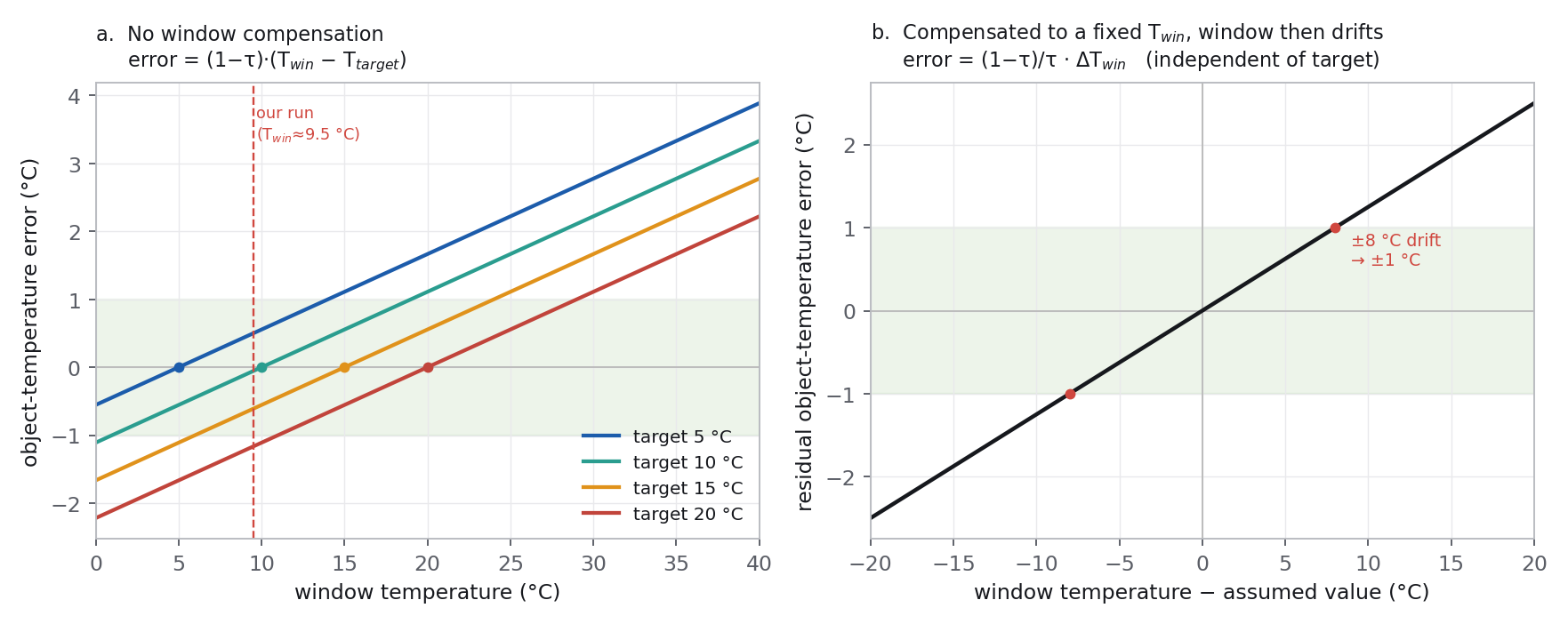
error = (1−τ)·(Twin − Ttarget).
Each target reads true only when the window sits at that target's temperature;
the error grows 0.11 °C for every °C the window departs from it.
b. Compensating to a fixed assumed window temperature re-centres the
zero but barely changes the slope
((1−τ)/τ = 0.125 °C/°C): a window that
drifts ±8 °C from the assumed value still costs
±1 °C, whatever the target.Neither static approach removes the sensitivity to a moving window. A fixed assumption — whether “no correction” or “correct to a nominal value” — is exact at one window temperature and drifts at ~0.11 °C per °C either side of it. Only a live window-temperature input flattens the slope.
Against a 1 °C object-temperature budget, the design levers are:
- A higher-transmission window. Every error in the figure
scales with
(1−τ). An anti-reflection-coated window atτ ≈ 0.95halves them against the0.89measured here; an uncoated window atτ ≈ 0.7nearly triples them. This is the single highest-leverage choice and it is a bill-of-materials line item. - Design the window to sit at die temperature. This does not by itself shrink the error — a cold scene under a warm enclosure still leaves a large window-to-scene gap. Its value is that it lets the existing die thermistor stand in as the window temperature, so the correction in panel b runs off a sensor already on the board with no added part. It requires a short conduction path from window to enclosure wall, a small recess, and shade from direct sun, and it has to be confirmed on the real mechanics — this bench run, with the window in a cold air column, is the counter-example.
- Measure the window temperature. A thermistor on the window frame — a few cents and one ADC channel — drives panel b's slope to near zero and makes the correction exact to the sensor's own noise, across the full scene and ambient range. It is the only option that holds accuracy when the enclosure can be sun-loaded well above a cold scene.
- Widen the target. At
±2 °C, a coated uncompensated window (τ ≈ 0.95, slope 0.05 °C/°C) stays in budget for any window temperature within ~40 °C of the target, and no window instrumentation is needed.
Recommendation. A coated window and a frame thermistor. The coating is where the accuracy is won or lost; the thermistor is the cheap insurance that keeps a sun-loaded or fast-changing window from spending the whole error budget. Designing the window onto the die thermally is worthwhile only if it removes the thermistor — and only after the product mechanics show the window actually tracks the die to within a few degrees.
Next run
Two runs have now shown the window sitting at the local air temperature, not the die. The blocking step is confirmed: a temperature probe on the window itself.
- Bond a PT1000 (or fine thermocouple) to the window edge and log it with
the die. Then
τ = 1 − Δ / (Twindow −
      Tscene)
is available per frame, andτseparates from the window-temperature term cleanly. Every warm-up without this yields only the compound(1−τ)·a. - Or hold the scene at a fixed temperature and sweep the sensor assembly temperature instead, so the die and window move together against a static scene.
- Repeat once the product enclosure exists, with the window mounted as it will ship, to get the coupling for the real geometry — and to check whether the sealed metal enclosure does hold the window at die temperature where the bench cannot.
- A fixed central pixel subset and better centring / tilt control at the longer standoff, to remove the residual per-pixel gradient.
Method & caveats
- Part: Panasonic AMG8854M01, the low-gain Grid-EYE variant — rated ±3.0 °C typical accuracy, 35.6° field of view [1][2]. Reference-spec §9-1 lists a window in the path as an accuracy-degrading condition requiring user temperature correction [1].
- The window run hit its 4 h safety cap before the block reached ambient; the PT1000 was still rising at 22.9 °C. The scene range is 4.9–22.9 °C against the no-window baseline's 2.4–21.3 °C; the comparison is restricted to the overlap.
- The no-window reading is a cubic fit in scene temperature, residual 0.12 °C rms. The die term was fitted and found negligible; it is not carried.
- Each capture is a 16-frame burst average. The 0.15 °C scatter
about the
Δline is between-capture temporal noise plus any slow drift between the two nights. - The two runs are on different nights. The scene is a shared physical reference (same PT1000, same spot, unmoved). Room temperature and the sensor's thermal environment are not controlled between runs; this is folded into the scatter.
- 238 windowed captures from the device read API joined to the PT1000 log on frame RTC, 232 used after the settling drop; 0 corrupt or stale frames in range.
References
- Panasonic. Infrared Array Sensor “Grid-EYE” Reference Specifications, AMG88** (document 160205). Radiometric model, temperature accuracy, notice-for-use §9-1.
- Panasonic. Infrared Array Sensor Grid-EYE AMG8854M01 (Narrow type), document pana-s-a0011553419-1 (30-Sep-20). 35.6° viewing angle, per-pixel optical properties, dimensions.
- Paes, V.F. et al. (2022). Calibration uncertainty of MEMS thermopile imagers for quantitative temperature measurement. Infrared Physics & Technology 120. ScienceDirect.
- Danjoux, R. Window and External Optics Transmittance. Infrared Training Center Technical Publication 60 (T560472_A). PDF. Radiance model for a window in the path, the contrasted-scene ratio method for τw, and the pixel-dependent transmittance of oblique rays.
- Madding, R.P. (2004). IR Window Transmittance Temperature Dependence. InfraMation 2004 Proceedings, Infrared Training Center / FLIR Systems (ITC 104 A). PDF. Band-averaged τ depends on window and target temperature; the correction is indeterminate when the two are equal.
- ASTM E1897-14(2022). Standard Practice for Measuring and Compensating for Transmittance of an Attenuating Medium Using Infrared Imaging Radiometers. ASTM International.
Further reading is collected under Literature.
Data: cold-pool run warmup_window_20260831_234510.csv (frame id 4223–4460, n = 238); elevated run warmup_window_elev_20260901_225017.csv (frame id 5781–6021, n = 238); baseline warmup_20260829_212910.csv (frame id 1786–1987, n = 173); device thermal read API. Published 2026-09-01, re-test added 2026-09-02.