Thermal sensor · flat-field characterization
Grid-EYE Flat-Field Study
Pixel-to-pixel non-uniformity of an AMG8854M01 8×8 thermal array, measured against a PT1000 over a three-hour 2–21 °C reference sweep, and the residual after per-pixel correction.
- Part
- Panasonic AMG8854M01 (35.6° FOV)
- Device ID
- cali.EGG68 (nRF9151)
- Target
- 1 in steel block, 3M black tape, insulated
- Reference
- PT1000 / Agilent 34401A
- Standoff
- 5.5 cm → 35 mm FOV footprint
- Scene sweep
- 5.6 → 23.4 °C (array mean)
- Die temp
- 25.7 – 28.1 °C (near-constant)
- Frames
- 183 / ~1 per minute, 2026-08-29 UTC
Summary
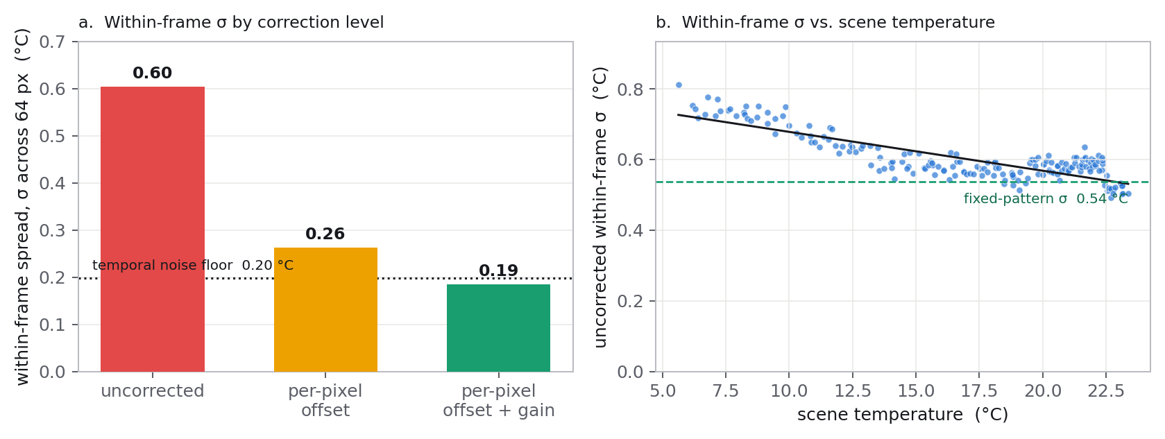
Raw pixel-to-pixel non-uniformity is 2.9 °C peak-to-peak (σ 0.60 °C across 64 pixels). The target is a 1 in steel block, thermally isolated; it is isothermal to well below the measurement resolution, and at 5.5 cm the sensor's 35.6° field of view covers only its central 35 mm. The pattern is the sensor. It is stable across the full 17 °C sweep. A per-pixel offset table reduces within-frame σ by 57%; adding a per-pixel gain term reaches 0.19 °C and leaves no spatial structure, even at the coldest scenes. The residual is temporal noise.
Raw pixel spread
2.9 °C
peak-to-peak · σ 0.60 °C
Fixed-pattern σ
0.54 °C
79% of the raw variance
After offset table
0.26 °C
−57% spread
After offset + gain
0.19 °C
−69% · = noise floor
Per-pixel deviation vs. scene temperature
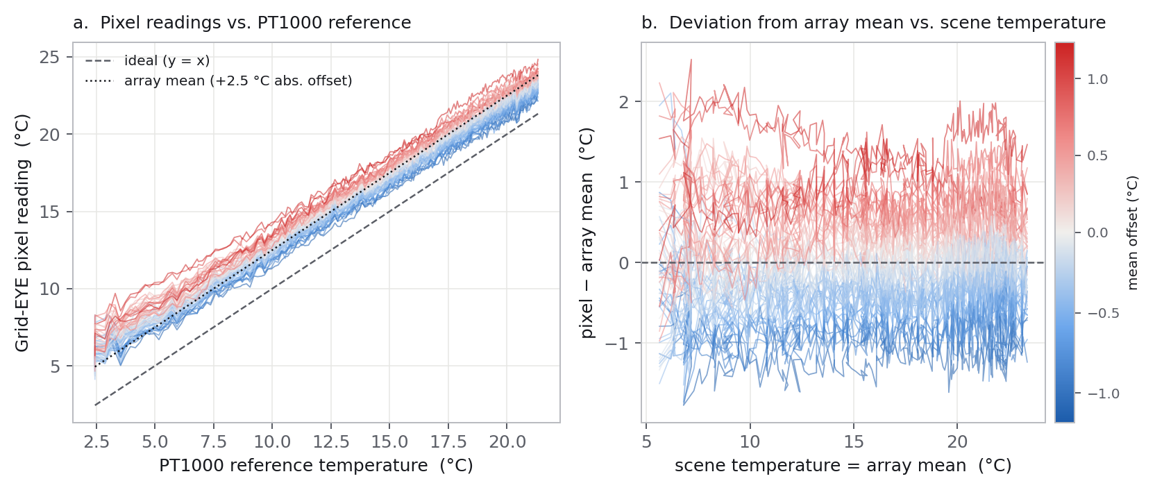
All 64 pixels track the reference linearly across the range (panel a). The array mean sits 2.5 °C above the PT1000 — an absolute-accuracy offset, separate from uniformity. Panel b plots each pixel's deviation from the array mean against scene temperature; the deviations are near-constant across the sweep. A pixel 0.8 °C above the mean at 6 °C is approximately 0.8 °C above the mean at 23 °C.
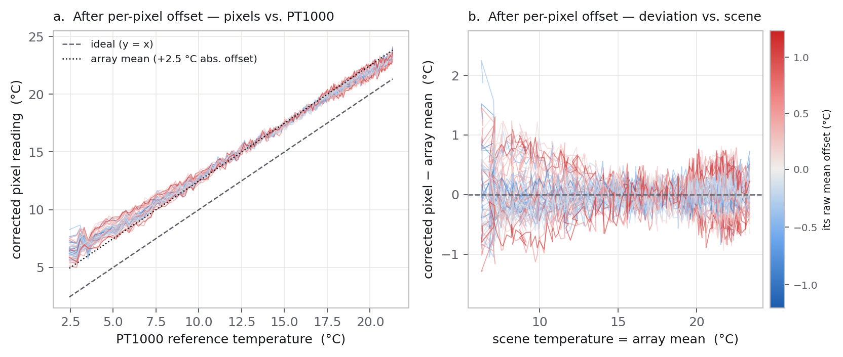
Because those deviations barely move across the sweep, one constant per pixel removes them. The figure below is the same 64 pixels and the same sweep, with each pixel's own offset subtracted — a 64-value table, the simplest possible per-unit calibration.
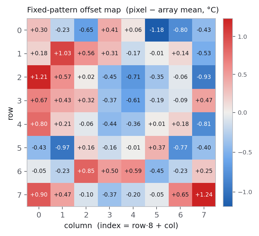
Fixed-pattern offset map
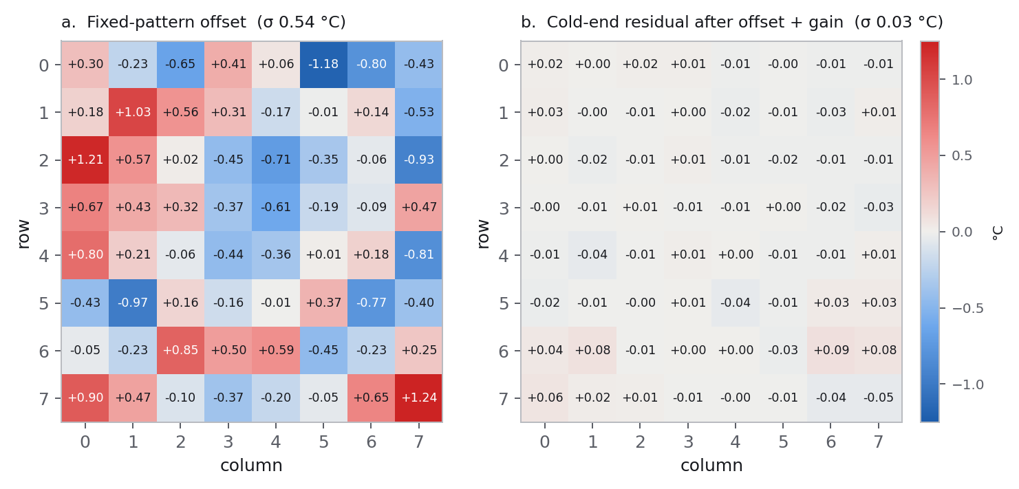
Each pixel's deviation from the array mean, averaged over the run — the
sensor's pixel-to-pixel non-uniformity. It has spatial structure: a diagonal
gradient, isolated outliers (pixel 5 at −1.18 °C,
pixel 63 at +1.24 °C), and it concentrates toward the
array edges — σ over the centre 6×6 is 0.45 °C, over the
centre 4×4, 0.31 °C, against 0.54 °C for the full array.
Consistent with lens vignetting and oblique optics at the field edge. Range
2.4 °C. This is the per-pixel offset table.
pixels[] array. Values in °C relative to the array mean.Offset and gain distributions
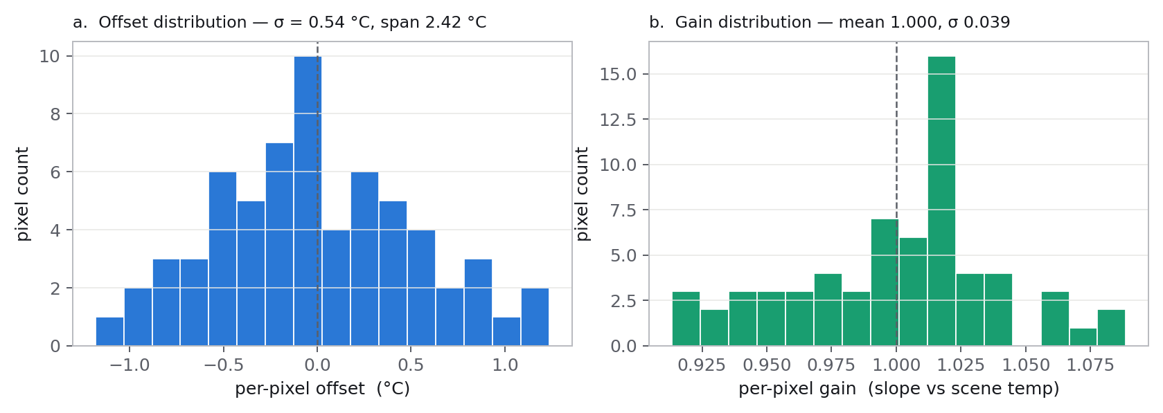
Per-pixel offsets are approximately normal about zero, σ 0.54 °C. Per-pixel gain is mean 1.000, σ 0.039, range 0.91–1.09 °C per °C, with its own diagonal spatial structure. The response slope is uniform to within 4%; the non-uniformity is mostly additive with a small multiplicative component.
Residual after correction
Per-pixel offset correction reduces within-frame σ from 0.60 to 0.26 °C. Adding the per-pixel gain term reaches 0.19 °C. The within-frame spread is higher at the cold end (0.70 vs 0.57 °C, panel b), but that is temporal noise, not pattern: it averages away. At the cold end the sensor images a scene ~16 °C below its own body while sitting in open air, which makes it more sensitive to draughts on the housing and die micro-drift. The time-averaged residual there, after offset + gain, is σ 0.03 °C (next figure) — nothing structured remains.
The correction table
Per-pixel offset in °C, subtracted from the raw pixel reading. Index order
matches pixels[].
| +0.30 | -0.23 | -0.65 | +0.41 | +0.06 | -1.18 | -0.80 | -0.43 |
| +0.18 | +1.03 | +0.56 | +0.32 | -0.17 | -0.01 | +0.14 | -0.53 |
| +1.21 | +0.57 | +0.02 | -0.45 | -0.71 | -0.35 | -0.06 | -0.93 |
| +0.67 | +0.43 | +0.32 | -0.37 | -0.61 | -0.19 | -0.09 | +0.47 |
| +0.80 | +0.21 | -0.06 | -0.44 | -0.36 | +0.01 | +0.18 | -0.81 |
| -0.43 | -0.97 | +0.16 | -0.17 | -0.01 | +0.37 | -0.77 | -0.40 |
| -0.05 | -0.23 | +0.85 | +0.50 | +0.59 | -0.45 | -0.23 | +0.25 |
| +0.90 | +0.47 | -0.10 | -0.37 | -0.20 | -0.06 | +0.65 | +1.24 |
1-term: T_corr[i] = T_raw[i] − offset[i] —
removes 57% of the spread; 64 constants.
2-term: T_corr[i] = (T_raw[i] − a[i]) / b[i], with
per-pixel intercept a[i] (°C) and gain b[i] —
residual 0.19 °C, no residual spatial structure; 128 constants. Gain map
b[i]:
| 0.916 | 0.934 | 0.939 | 0.961 | 0.993 | 1.000 | 0.996 | 0.993 |
| 0.913 | 0.930 | 0.944 | 0.951 | 0.995 | 1.022 | 1.015 | 1.008 |
| 0.917 | 0.947 | 0.964 | 0.985 | 1.017 | 1.018 | 1.012 | 1.009 |
| 0.958 | 0.955 | 0.937 | 0.979 | 1.015 | 1.017 | 1.014 | 1.019 |
| 0.973 | 0.976 | 0.976 | 0.999 | 1.021 | 1.019 | 1.019 | 1.017 |
| 0.985 | 0.986 | 1.005 | 1.012 | 1.025 | 1.023 | 1.030 | 1.038 |
| 1.007 | 1.002 | 0.999 | 1.017 | 1.034 | 1.020 | 1.057 | 1.067 |
| 1.057 | 1.060 | 1.022 | 1.030 | 1.040 | 1.045 | 1.089 | 1.079 |
Method & caveats
- Part: Panasonic AMG8854M01, the low-gain Grid-EYE variant — rated ±3.0 °C typical accuracy, NETD 0.20 °C at 10 fps, −20 to +80 °C operating range [1].
- The uniformity reference is the array mean, not the PT1000. This isolates pixel-to-pixel structure from the 2.5 °C absolute offset (emissivity, field-of-view fill, window, distance), which is a separate calibration.
- Target uniformity. The AMG8854M01 field of view is 35.6° [4] (footprint 0.643·d); at 5.5 cm that is a 35 mm circle in the centre of the 63.5 mm block, ~14 mm clear of every edge and of the insulation. A 1 in steel block warming at ~6 °C/h equilibrates internal gradients in ~25 s (Biot « 1), so it is isothermal across that footprint to well below the measurement resolution. The pattern — offset and gain — is the sensor, not the rig.
- A single target proves relative pixel-to-pixel uniformity, not absolute response. An independent isothermal target (Peltier plate) at fixed setpoints would confirm the gain map.
- Die temperature stayed within 25.7–28.1 °C. Drift of the pattern with sensor temperature is not characterised; the table applies near 27 °C die temperature.
- Each capture is a 16-frame burst average (~1.6 s); the sensor's own noise contribution is ~0.05 °C (NETD 0.20 °C over √16 [1]). The 0.19 °C after-correction residual, and its rise to ~0.26 °C at the cold end, is between-capture temporal noise — larger where the scene-to-sensor contrast is largest and the sensor is exposed to air. Shielding the housing from draughts, or more averaging, brings it down.
- 183 captures, from the device read API joined to the PT1000 log on frame RTC;
0 corrupt or stale frames in range. Per-pixel model fitted by least squares,
pix[i] = a[i] + b[i]·mean. Temporal noise is the residual σ of each pixel about its own fit.
Where the correction lives
The AMG8854 has no user-writable non-volatile memory. Its R/W registers (power, frame rate, moving average, interrupt thresholds) are volatile and reset on power-cycle; the 64 pixel registers are read-only; reserved registers must not be written; the factory calibration is internal to the ASIC and not readable [1]. Panasonic's application note states that pixel-to-pixel calibration is performed by the customer in software [2]. Reference-spec §9-1 also lists sudden sensor-temperature change, nearby heat sources, air currents, and a window in the path as accuracy-degrading conditions requiring user temperature correction [1]. The correction is applied on the host, and not necessarily in the firmware image. Multi-point per-device correction below the datasheet typical accuracy has been demonstrated for the AMG8833, the high-gain sibling of this part [3].
The table is data. It belongs in non-volatile storage on the nRF9151 — an NVS partition in internal flash, or the 16 MB SPI NOR (IS25LP128F) in the product BOM. Firmware reads it at boot and subtracts the per-pixel offset before building the payload; with no table loaded, frames pass through uncorrected.
The table is written once per unit before deployment
(Pre-deployment calibration), and replaced in service by a
config-object or LwM2M downlink (64 × int16 ≈ 128 bytes),
or by the device re-running its own routine — a memory write, never a firmware
reflash. The config hash in the production payload identifies the cal
version per device, preserving traceability with the correction applied
on-device.
Storage and compute. The table is 130–300 bytes
(64 int16 offsets, an optional gain term, a header) — under 1% of an
8–32 KB NVS partition, written a few times over the device's life.
Applying it is 64 int16 subtractions per frame: ~1 µs
/ ~10 nJ on the Cortex-M33, against ~25 ms for the I²C frame read and
seconds of modem transmit time. Neither storage nor compute constrains the choice.
Recommendation. The per-pixel offset table is stored on-device in NVS / SPI flash, written once per unit at calibration and updatable remotely. It is a property of the sensor die and stable across temperature. On-device correction transmits flat data and permits tighter quantisation of the ~0.2 °C residual over the metered link. Raw frames continue to the database only during bench refinement of the table. Installation-dependent corrections — die-temperature model, window transmission, emissivity — remain server-side. Fixed-pattern offset is a device property; environmental corrections are installation properties.
Pre-deployment calibration
Each unit receives its per-pixel table before it ships. The device runs a short routine against a stable reference at two or three temperatures, fits a per-pixel offset (optionally offset and gain), and writes the coefficients to its cal partition over the local link — USB-serial on the bench, BLE in the product.
The table is specific to that sensor die: fixed-pattern non-uniformity is intrinsic and varies from unit to unit, so this step is per unit. The installation-dependent terms — window transmission τ, die-temperature response — are characterised once on a small sample at product bring-up, not per unit.
The reference plate, the number of temperature points, and the on-device command interface are detailed in Production Calibration.
Next run
- Apply the offset table and repeat the sweep. Expected pixel-to-pixel peak-to-peak: below 1 °C.
- Confirm the offset and gain maps against an independent isothermal target — a Peltier plate at fixed setpoints, not a warm-up transient.
- Separate run with the sensor assembly heated, to fit the die-temperature term (die barely moved here).
- Shield the sensor housing from air currents to bring down the cold-end temporal noise.
References
- Panasonic. Infrared Array Sensor “Grid-EYE” Reference Specifications, AMG88** (document 160205). Register map, NETD, temperature accuracy, operating range, notice-for-use §9-1.
- Panasonic. Infrared Array Sensor Grid-EYE AMG8854M01 (Narrow type), document pana-s-a0011553419-1 (30-Sep-20). 35.6° viewing angle, per-pixel optical properties, dimensions.
- Panasonic. Grid-EYE Characteristics (application note) — “Characteristics after Calibration of the Pixels”: customer-side per-pixel software adjustment.
- Paes, V.F. et al. (2022). Calibration uncertainty of MEMS thermopile imagers for quantitative temperature measurement. Infrared Physics & Technology 120. ScienceDirect. See Literature.
Data: PT1000 log warmup_20260829_212910.csv + device thermal read API, frame id 1786–1987, n = 183. Published 2026-08-30, revised same day after confirming the sensor is the 35.6° narrow-angle AMG8854M01 — corrected the field-of-view geometry, which removed the earlier “outer-pixel rig artefact” reading.