Dated notes from the bench — what I'm working on, what it
showed, and where it went wrong. This is the Grid-EYE thermal-sensor thread of a
personal project around remote environmental sensing, built on the nRF9151. Rough
by design; a working phase, not finished things.
BLE bridge: a scheduling bug, a host-side leak, and the real rate ceiling
Continued the wired nRF9151 → PAN1781 → BLE
relay path from the previous session, this time chasing down why raising the
Grid-EYE commissioning rate kept breaking the link. First found a scheduling
bug on the nRF9151 side: the firmware re-armed its next capture as
“now + period” after a blocking I²C read
and UART send, so the two costs stacked on top of the requested period every
cycle — a requested 100 ms rate was landing at ~150 ms on the
wire, confirmed directly on the scope. Fixed by anchoring to a running tick
target instead of re-arming off “now” each time.
A ~4h09m unattended overnight run at 200 ms surfaced a second, separate
bug: the host-side viewer app had an unbounded console widget that grew to
4.3 GB resident and got killed outright by the kernel's OOM killer.
One missing setMaximumBlockCount() call. While in there, also
added manual min/max color-scale controls to the Grid-EYE and LiDAR live
views — the auto-ranging had been renormalizing the color map to each
frame's own min/max, which quietly makes frame-to-frame comparison
meaningless.
The main find was on the PAN1781 bridge itself. Fast commissioning rates
(20 ms and below) reliably crashed the link within seconds, and it
looked at first like a bandwidth problem — it wasn't. Real measured
throughput at every rate tested was under 1.5 kB/s, nowhere near the
link's own ~12 kB/s isolated ceiling. The actual constraint was
packet count per frame against the BLE connection interval's fixed drain
capacity: each ~140-byte frame needed about three small BLE packets at the
bridge's old 60-byte chunk size, and a fixed 1024-byte firmware heap had no
bound on how many of those packets could queue up if the drain ever fell
behind — which is exactly what a fast commissioning rate did. Added a
bounded, drop-oldest queue as a safety net first (turns an unbounded-queue
crash into graceful data loss, nothing more), then went further: resized
the relay buffer, BLE MTU, and Data Length Extension to fit one whole
Grid-EYE frame into a single BLE packet instead of three, and grew the
firmware's heap using RAM already freed by trimming unused logging and
security features earlier in the project.
Result: a 20 ms commissioning rate that previously crashed the link
within 17–48 seconds, every time, now runs clean — 0.02% checksum
failure rate, steady heap, no drops. Treated this explicitly as a chance to
actually learn the BLE link mechanics properly (connection intervals, PHY,
MTU vs. Data Length Extension, packet count vs. raw bandwidth) rather than
just patch the symptom, since the same knobs will matter again on whatever
comes after this project.
2026-09-19
LiDAR: first working bring-up, and what it took to get there
cal tof init then cal tof raw now run cleanly on
real hardware — firmware upload, resolution set, ranging start, and a real
8×8 distance frame, over the same I²C bus the Grid-EYE already shares.
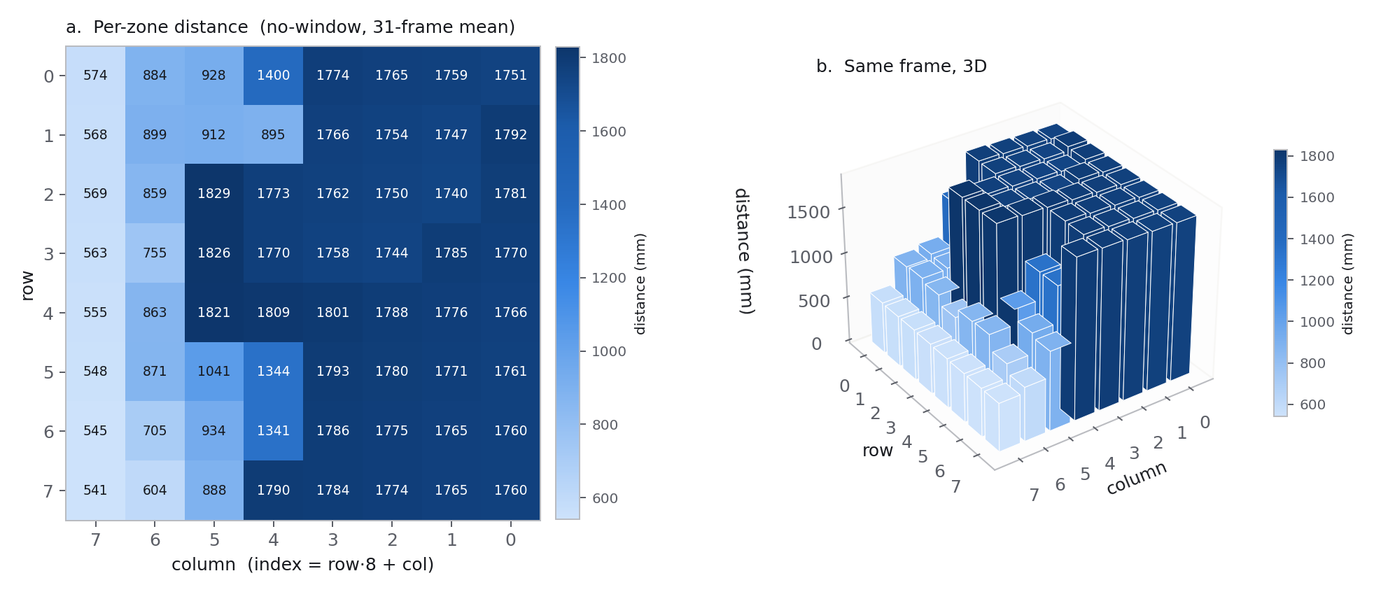
The first frame was physically coherent on sight: columns 0–4 read a
consistent ~1.8 m (the ceiling above the bench), column 7 read
~550 mm (a nearby shelf edge), with a clean diagonal transition between
the two — exactly the bench scene in front of the sensor.
The first clean frame, read two ways — heatmap for the
exact per-zone number, a 3D block plot (bar height = measured distance) for
how the scene actually looks. Settled on keeping both after a direct
side-by-side check showed neither alone was enough. Click for full
size.
Two real software bugs stood between “wired up” and this,
both found by methodical isolation — a second, never-stressed board
failed identically, which is what pointed at software rather than a damaged
part. First, lidar_is_alive() never set the device address before
calling into the ULD driver, so a standalone liveness check (before
init had run) silently addressed the I²C general-call address
instead of the sensor, producing a NACK indistinguishable from a dead chip.
Second, the ULD driver's multi-byte register write hit the nRF TWIM driver's
internal concatenation-buffer limit on anything over 16 bytes — our
write chunks run up to 512 — which the driver itself reported as an
ENOSPC naming the exact devicetree property. Fixed by building the
combined write buffer locally and sending it as one plain write instead of
relying on driver-level message concatenation.
On the electrical side, connecting the sensor to the shared bus produced a
sustained ~14 MHz oscillation on both SDA and SCL, swinging well past the
1.8 V bus rail. Root cause: the board's onboard level translator uses
edge-triggered, auto-direction sensing, which is a known bad combination with
an already RC-limited, weak-pullup open-drain bus — the translator's own
direction logic was reacting to the bus's own slow charge curve. A
100 Ω series resistor between the shared bus and the translator
settled it completely, with negligible voltage drop at these pullup values.
The most interesting bug wasn't electrical at all. Even after the wiring was
solid, ranging failed intermittently in a way that survived a full reinit and a
power cycle — both of which rule out corrupted device state, so the cause
had to be elsewhere. It was a missing bus-arbitration lock: the Grid-EYE's
periodic capture (main thread, on a wall-clock timer) and the LiDAR's own
multi-step ranging sequence (shell thread) could interleave, since Zephyr only
serializes individual low-level transfers, not each device's operation as a
whole. A capture landing mid-sequence in the LiDAR's start/wait/read/stop chain
was enough to break it. Fixed with one shared mutex held for each device's
entire I²C-touching operation, not just around each transfer —
validated by computing the next collision window and firing continuous ranging
calls straight through it: 50 of 50 succeeded. Worth remembering generally:
sharing a bus needs a whole-operation lock, not just per-transfer safety, and
that requirement will come back when the SPI bus picks up a second device.
The infrared window is confirmed: a UQG Optics ZSW-132 —
Ø13 mm by 2 mm, multispectral zinc sulphide, uncoated. Its
datasheet thermal conductivity is 27 W/m·K, so the temperature
difference across the 2 mm thickness works out to a few thousandths of a
degree under any realistic heat flow. The window is effectively one temperature
front to back, which means a single sensor bonded anywhere on it reads the whole
part. That closes a question from the window calibration work — one PT1000
on the edge is enough.
Multispectral ZnS is soft (Knoop hardness 160, about the same as calcium
fluoride) and marks easily, so I wrote up handling and cleaning notes for
myself: blow the grit off first, drop-and-drag with spectroscopic-grade
methanol or acetone, never a dry wipe, no ultrasonic bath. A fine PT1000 is
glued to the window edge now with thermal adhesive, curing overnight.
2026-09-02
Lifting the window; and the sensor's own warmth
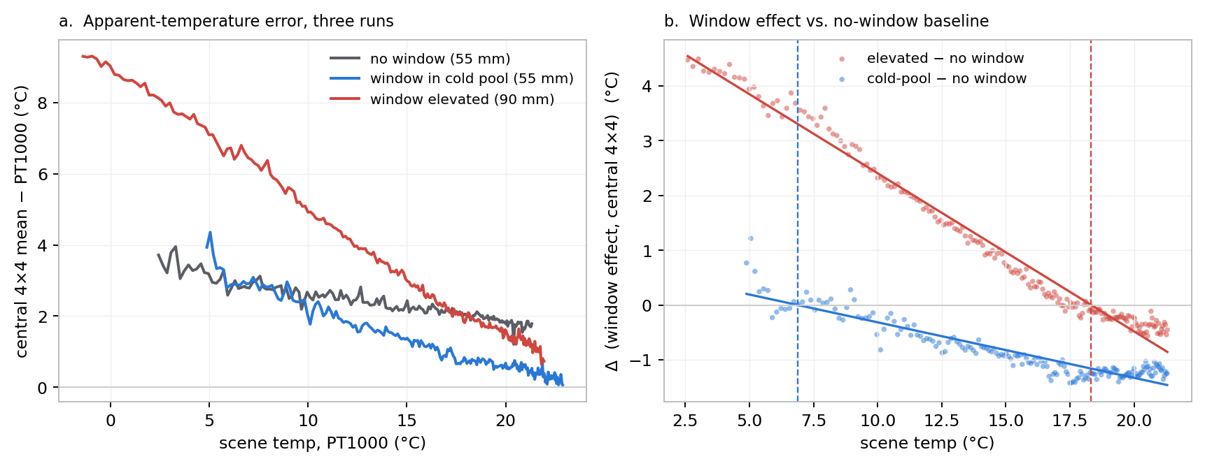
Re-ran the window warm-up with the sensor and window raised 35 mm clear
of the insulation chimney, to test whether the window would then settle at the
sensor's own temperature. It did not. Backing the window temperature out of the
radiometric model, it moved from about 7 °C (sitting down in the cold
air pool) to about 18 °C (room air) — not to the ~26 °C
die. The window tracks whatever air is around it. The bench can't reproduce
“window equals sensor temperature”; that has to come from the sealed
enclosure, not the optics.
Three runs compared. Raising the window (red) moves where its
effect crosses zero from ~7 °C to ~18 °C — toward room
air, not toward the sensor. Click for full size.
Separately, measured the Grid-EYE's own self-heating. Running continuously it
sits about 2 °C above ambient, with a package thermal
time constant near 2.5 minutes. Duty-cycling the capture to once every ten
minutes with the sensor asleep in between should bring that down to a few
hundredths of a degree.
Also spent time on housekeeping — pulled the bench runs into dated
experiment folders and archived the server tables before they grow further.
Worked through the window warm-up data. The window shifts the apparent
temperature by a scene-dependent amount — roughly
+0.4 °C when the scene is cold, −1.1 °C near ambient,
crossing zero around 9–10 °C. A pure transmission loss can't do
that; a cold window with a fixed transmission would push every reading the same
direction. The window was running at the chimney's cold-air-pool temperature,
not the sensor's, so one warm-up only pins the combined term
(1−τ)·a ≈ 0.13, not the transmission on
its own.
Read into the thermography literature and found the FLIR technical
publication and an InfraMation paper describe exactly this method and exactly
this dead end — the transmittance correction goes indeterminate as the
window and target temperatures converge. Added a literature list to the project
pages and worked out the accuracy budget for an uncompensated window.
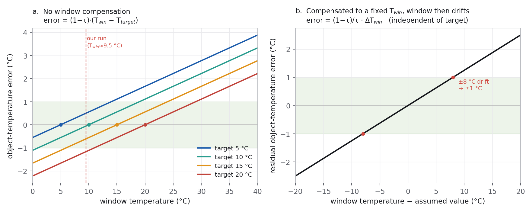
What an uncompensated window temperature costs. Each target reads
true only when the window happens to sit at that temperature; correcting to a
fixed assumed value re-centres the error but barely changes the slope. Click
for full size.
Set up the window warm-up: the same cold-steel-block-warming-to-ambient sweep
as the flat-field work, but with the ZnS window glued to the front of the
Grid-EYE and the same PT1000 unmoved on the block as the shared reference. Four
hours, automated, logging block temperature against the sensor frames.
2026-08-30
Flat-field study, and a correction to the geometry
Published the pixel-to-pixel uniformity write-up. The array's raw spread is
about 2.9 °C peak-to-peak. A per-pixel offset table removes more than
half of it; adding a per-pixel gain term takes the residual down to the sensor's
temporal noise floor with no spatial structure left. The block target is
isothermal to well below the measurement resolution, so the pattern is the
sensor, not the rig.
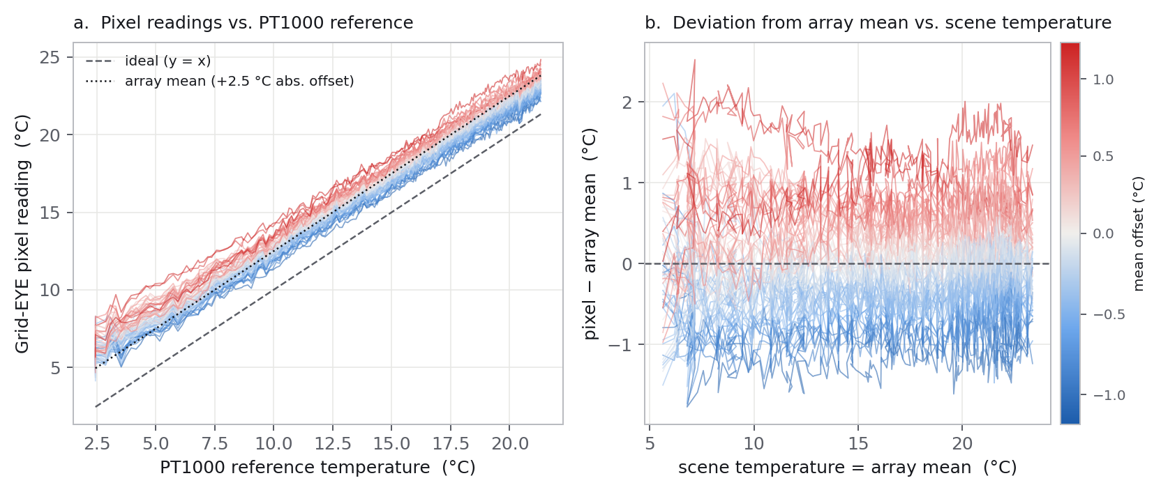
All 64 pixels tracking the reference, and how far each sits from
the array mean — the deviations barely change across the whole sweep,
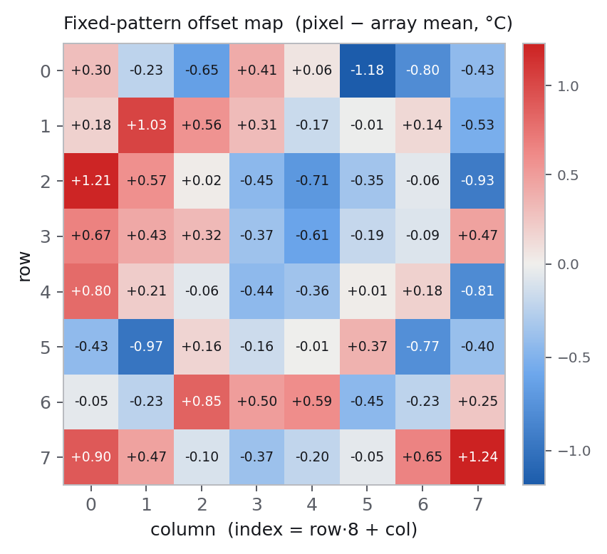
which is what makes a fixed correction table work. Click for full size.The actual pixel data — each pixel's run-averaged offset
from the array mean. A diagonal gradient, a few isolated outliers, and it
grows toward the edges, consistent with lens vignetting. This is the
correction table. Click for full size.
Also corrected a mistake I'd been carrying: the bench sensor is the
narrow-angle AMG8854M01 with a 35.6° field of view, not the 60° part I'd
assumed. That changes the footprint on the target to 0.643·d
and, usefully, means an earlier “outer-pixel rig artefact” reading
was really just the sensor's own pattern. Revised the pages.
Sketched a production calibration approach — a Peltier plate at three
setpoints, an on-device least-squares fit, coefficients written to flash.
First real check of the thermal channel against an independent reference: a
PT1000 on the bench block, read by an Agilent 34401A, against the Grid-EYE
frame. Once the PT1000 was on the same surface the sensor actually
images — not tucked behind a protective layer — agreement landed at
0.5–1.3 °C, inside the sensor's datasheet accuracy. Started an
automated warm-up sweep to get a full curve rather than a single point.
2026-08-22–23
Field test plan and bench rigs
Wrote up a minimal real-world test — press a button, capture a frame,
send it over CoAP, store it, watch it appear on a web page — deliberately
stripped of everything that wasn't the core path. Started the enclosure CAD and
a two-zone contrast rig: a Peltier-driven target on an isothermal plate, for
measuring apparent-temperature error against range and window state.
2026-08-17–21
Porting to the production module, and a counterfeit debugger
Began porting the working Grid-EYE firmware to the LooUQ MTC2-N9151 —
the module intended for the actual product, pre-certified for NB-IoT and
satellite. The first J-Link I bought for the bring-up turned out to be
counterfeit: it fails SEGGER's own anti-counterfeit handshake, which was clean
to confirm by running it side by side against the dev kit's genuine onboard
debugger. Ordered a real one. Also found on paper that the Grid-EYE's I²C
lines are swapped between the two boards — caught before the first flash,
not after.
2026-08-14–16
Grid-EYE bring-up
Got the Panasonic Grid-EYE reading over I²C on the nRF9151 — all
64 pixels plus the onboard thermistor, decoded from the sign-magnitude register
format and checked against the datasheet's worked examples, with the array
orientation mapped. Forked it out of the CoAP debug harness into its own
project. Added sensor sleep and wake control with the documented power-up
sequence, and moved the capture timing into one place so a duty-cycle policy has
somewhere to live.
Written by Eggert Gudmundsson. Updated 2026-09-29.